

Fred Thirty-two gave me a call this last weekend. Could I help him plot an airfoil?
Sure, I sez, and commence doing so. After a minute or so I realize there is a pregnant pause bulging out of the telephone. “Hello?”
Ummm, Fred Thirty-two says. Also, ah, er, uh and eh. Finally, could I mebbe show him how to do it?
Turns out, Fred Thirty-two has a problem with verbal instructions. Written ones, too, but I didn’t find that out until he was sitting across from me in the patio. He’s a trim looking fellow in his fifties, a working man judging from his hands and clothes. Not a lot to say at first, which I took to be nervousness. Got him some coffee, showed him pictures of the grandkids. Once he warmed up I was delighted to find he had a keen sense of humor. A bigger surprise is that he’s probably smarter than me. Based on his emails, I’d expected the opposite since his spelling is uniquely adventurous and his grammar like a literal translation of German. Talking to him one-on-one, it doesn’t take long to figure out he probably suffers from dyslexia. Which isn’t necessarily a problem; being dyslexic doesn’t mean a person is dumb nor insensitive, although it can be something of a challenge in a classroom since guys like Fred usually learn best by actually doing the work. Which can be horrifyingly difficult if the subject is history, government, geography and so on - - the core subjects our educational system requires for graduation.
I was an instructor in the Navy and ran into cases similar to Fred’s in that their dyslexia wasn’t recognized before they’d already flunked out of school and were shit-canned by society. (Fred is in ‘Facilities Engineering,’ by the way. Meaning he pushes a broom.)
Fred has recently acquired a used computer and is learning how to use it; he thinks the OS is Windows 95. He’s also got a copy of DeltaCAD and has used it to download most of the HVX files. He’s a good mechanic and a fair machinist, having used a mild steel steam-pipe flange to make the drive-hub for the coaxial dynamo, which was what told me he’s smarter than the average bear.
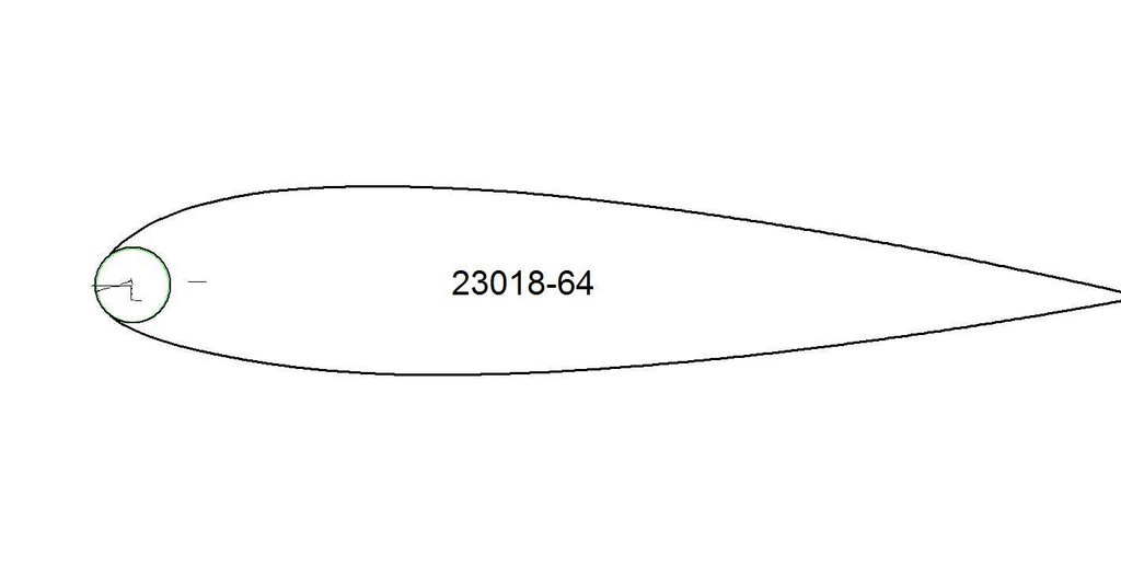
Fred showed me some neatly done sketches and several sheets of figures derived from the 1960 edition of the ‘Amateur Aircraft Builder’s Manual.’ From what I saw, his Dream Machine didn’t break any of the rules, although it was pretty big, designed around a liquid cooled industrial engine. Right now he needed a hand turning the NACA coordinates of an airfoil into ribs for a tapered wing, 64 inches at the root, 48 at the tip.
The 230-series isn’t an airfoil I’m familiar with. I go into the house, dig around for Abbott, grab the lap-top and before you can say ‘Theory of Wing Sections’ we’re sitting there, sipping coffee and having a high old time keying the coordinates of the 23018 into DeltaCAD.
NACA cites 16 x-y coordinates for each surface of the airfoil, listed as a percentage of the chord; 18 if you count the 0% and 100% x-location, which nobody does. Fer instance, the upper surface 5% coordinate for the 23018 is 6.92% of whatever chord you’re using. In DeltaCAD you simply draw a line equal in length to the chord, select the POINT function, click on the start of the line as your initial location (ie, 0,0) then enter .05*64, .0692*64 and hit enter. (The asterisk means to multiply the second number by the first.) That will give you a dot precisely 3.2" back from the leading edge (ie, the x-location) and 4.4288" above the chord-line (ie, the y-location). If you were doing the lower surface you’d add a minus to the y factor (ie, .05*64, - .038*64).
See how it works? You’re letting DeltaCAD do the calculating. Telling it .05 * 64 means you want it to use the value equal to 5% of 64 inches (for the x-location), whereas telling it .0692 * 64 tells it to calculate the value for the y-location. Since the POINT function expects the x and y to be separated by a comma, you put one in: .05 * 64 , .0692 * 64. Hit the big red button and there’s your point. Do that thirty-two times, connect the dots and there’s your airfoil.
Not very elegant but it gets the job done. So long as the rib (and wing) is being hand-fabricated, using just sixteen coordinates for each surface works just fine. Modern coordinate systems plotting points as close as every thousandth of an inch of chord (!) were developed to satisfy the input of CNC machines and super-computers. Building a rib out of quarter-inch sticks, the accuracy and precision of the resulting surfaces depends largely upon how willing the wood to follow the curve. Ditto for banging ribs out of aluminum or sanding the wing-surface to match a few templates.
Unfortunately, Fred Thirty-two never learned to type by touch. I watch him hunt & peck for a couple of coordinates, determined look on his face - - but a happy one - - until I scream in frustration, snatch the keyboard away and show-off at a hundred words per minute. (Entering the coordinates is the EASY part of the job. Takes mebbe ten minutes. The tricky bit is turning the airfoil into patterns and jigs.)
Once we get the coordinates entered I select the SPLINE function and connect the dots. DeltaCAD turns it into a smooth curve and there’s the 23018 airfoil flying on the computer’s screen, a fat, jolly looking teardrop that makes you think of Ford Tri-motors.
Pure joy on the face of Fred Thirty-two. Just having the basic airfoil in front of him offered bags of information he didn’t have before, such as spar depth (nearly 12") and approximate fuel tank capacity. The Dream had come a bit closer.
To get the airfoil out of the lap-top I took it into the house, laid a two inch grid of faint blue lines over the drawing, transferred the file into another computer and printed it out. It took fourteen sheets of normal sized typing paper. I showed Fred how to use a thread on a sliding glass door to align the sheets. After taping them together I kicked around under the workbench, found a scrap of eighth-inch doorskin ply, spritzed it with spray glue then eased the drawing onto it. Sawn near the line and then sanded to it, the plywood can serve as a pattern. But so will the original drawing, now that it exists as a file Fred can load into his computer and manipulate with DeltaCAD.
DeltaCAD’s simplistic POINT function and spending ten minutes hand-entering coordinates is the ultimate in Lo-Tek but this an inexpensive tool anyone can master. The fat 23018 may not be the ideal airfoil for Fred’s Dream Machine but if it doesn’t work out he now knows how to generate ANY airfoil for which he can find x-y coordinates, an option he didn’t have just a few days ago.
-R.S.Hoover
PS - His name isn’t Fred, of course. But after posting messages about Flying on the Cheap, inexpensive methods of converting VW engines for flight and using locally available lumber, I’ve been contacted by a surprising number of ‘Freds’ here and abroad who are doing exactly that.
PPS - I’ve never been asked to autograph an airfoil before. Thank you, Fred. I consider it quite an honor.
No comments:
Post a Comment