Flying, homebuilt airplanes, working with wood, riveted aluminum, welded steel tubing, fabric, dope and common sense. Gunsmithing, amateur radio, astronomy and auto mechanics at the practical level. Roaming the west in an old VW bus. Prospecting, ghost towns and abandoned air fields. Cooking, fishing, camping and raising kids.
Thursday, August 23, 2007
AV - Crankcase Basics - II
Before wasting any time here, go read:
http://bobhooversblog.blogspot.com/2007/05/av-crankcase-basics.html
...especially the part where I say:
you will need nuts and washers and bolts to fasten the case studs and parting-line. Here again, there are kits available but most are the shoddiest stuff imaginable and price is no guarantee of quality. The nuts and washers may have a wash of zinc plating, good for at least a week’s exposure to the weather. Or they may not. And you can toss the ‘exhaust nuts.’ They are copper plated steel. (The good stuff is bronze.) Before you can use any of this crap on an engine you must provide it with some form of corrosion protection. If you don’t, not only with the nuts rust to the studs, you’ll see galvanic corrosion between the washers and the crankcase that will eventually cause the fastener to loosen.
Although any after-market VW retailer will be delighted to sell you that shoddiest stuff imaginable, the hands-down winner is J.C.Whitney because they usually charge more than most.
Back when I had hair I wrote an article ('Cows') explaining why it was a good idea to not buy VW parts from J.C.Whitney. Fig 1 offers a nice example of why this is still true. In the picture you can see the supposed 140-piece contents of JCW's catalog #xxx380749. (The 'xxx' is the catalog prefix which changes from minute to minute but the basic number stays the same.) A fellow chugger paid $15.99 plus shipping for what you see in the photo only to discover that most of the fasteners were unusable or not needed. (As of 8/23/07 the price is $17.99 making it even worse.)
Here's why: See those sixteen M10 nuts? (Lookit Fig 1A) Didja notice the M8 head stays illustrated in the 'Crankcase Basics' article? The M10 nuts & washers are for a pre-1971 crankcase, which you are not using if you're building your engine an a Universal Replacement Crankcase. And if you are starting out with a used crankcase then the odds are you already have a perfectly suitable collection of M10 nuts & washers.
Indeed, other than the six M12 nuts shown in Fig 1B everything else shown in Fig 1 is available from the local Borg for significantly less than JCW prices. But even then, the JCW parts are not the sort of stuff you want to use when assembling a good engine.
A point often overlooked by the shade-tree types is that several VW fasteners are also oil seals. The washer and in some cases, the nut, must be prepared and installed in such a manner as to prevent oil from leaking out around the fastener. The best example of this is the four lower head stays on each side of the engine that are terminated inside the valve galleries but this rule also applies to the six M12 nuts, the pair of M8 studs adjacent to the #1 cam bearing and the two M8's that support the #4 Main Bearing.
Fig 3 shows the type of M12 nut used on later-model Volkswagen engines. The red ring is an elastomeric seal that bears against the heavy washer which itself is bedded in Permatex or other non-hardening sealant, another of those 'unimportant' details casually disregarded by non-professional engine builders, most of whom insist that it's normal for the VW engine to leak like a bitch. Being a stock VW part, the nuts are commonly available but their price varies wildly from an honest thirty-five cents or so to more than a dollar from the typical Screw-the-Newbie suppliers (who always seem to run the biggest ads :-)
I'll cover the proper application of fastener sealants at the appropriate time. Or you can dig it out of the VW factory service manuals.
But the most regrettable failing of such hardware kits is their failure to provide real exhaust nuts. What you get is a regular steel nut with a wash of copper plating, guaranteed to last for at least thirty minutes before welding itself to the exhaust stud. What you want is a bronze or brass nut, installed upon a bronze, brass or copper washer with a lavish application of anti-seize compound. If you have a small lathe these are easy to make from bar stock but they are also available from the Usual Suspects.
Fig 4 shows a baggie of brass exhaust nuts sized to accept a 12mm wrench, allowing them to be used on the lower exhaust studs without interference when using a custom-built exhaust manifold as is common with aircraft engines.
To me, an engine is a forever kinda thing. There is no Magic Bullet. The reliability of any machine is nothing more than a reflection of paying the keenest possible attention to the smallest details of its assembly. Using the correct fasteners is a big part of that.
-R.S.Hoover
Sunday, August 19, 2007
AV - Chugger's Progress - IV
A recent thread ('REAMING') on the Usenet Newsgroup devoted to homebuilt airplanes brought to light the fact that a basic tenet of building with wood was so misunderstood as to make the job of attaching fittings far more difficult and time consuming than it needs to be. The basic tenet is this: When a fastener penetrates a wooden member for the purpose of transferring the primary load, the hole for the fastener ALWAYS begins as a loose, over-size fit.
There's two reasons for this rule, the first being the fact wood isn't very strong, the second that 12% to 15% of any piece of wood consists of water.
For example, in the first case let's suppose you're attaching a wing-lift fitting to a spruce spar. Sitka Spruce is only good for a few hundred pounds in tension. If we were using quarter-inch bolts to secure the fitting we might very well drill a 3/4" hole instead of the expected 1/4". Why? Because that would allow us to install an aluminum or hardwood bushing into the spar, increasing the tensile load-limit per fastener by approximately 8x for hardwood and more than 20x if we use aluminum. The fit of the bushing in the spar doesn't have to be especially precise since it will be installed using a gap-filling epoxy such as JB Weld for the lo-buck homebuilder or 3M's 'Scotch Weld' structural adhesive for the Rich Folk. (The aluminum bushing would of course be reamed to matched the fastener.)
In the second case, since the rule is to never allow a fastener to come into direct contact with wood, we would start with a hole at least 1/64th over-size and butter a suitable sealant into the hole. Additional sealant is applied to the fastener which is then installed. If the fitting requires periodic dismantling (and all primary load carriers do, to facilitate inspection) then the bolt would be treated with wax or other release agent before being coated with sealant.
The sealant would typically be an epoxy or resorcinol glue -- something 100% waterproof (*). The engineering behind this procedure is based on the fact that all modern-day adhesives are stronger than wood.
Back in the Good Ol' Days, whenever that was, the typical sealant was varnish and frankly, it didn't do a very good job. A hole is mostly end-grain and to ensure it was adequately sealed you'd often have to flood the hole with varnish for an hour or more, allow it to cure then re-drill the hole. Not many bothered to do so. Instead, they'd hook a patch on a piece of safety wire, saturate the patch with varnish and pump it back and forth through the hole a few times. This was a virtual guarantee that the fastener would corrode down inside the hole and become almost impossible to remove.
Often times a cursory examination of an airframe or set of plans reveals fittings and fasteners that appear to violate sound engineering practice. In such cases it's always wise to take a closer look. A massive landing gear fitting that appears to use nothing more than a couple of AN3's in tension usually proves to bear the landing loads in compression, the AN3's serving only to hold the fitting in position and not subjected to any portion of the landing load. I mention this because these are areas where home-builders tend to improve on the design by replacing the perfectly adequate #10 fasteners with quarter-inch or even 5/16".
Finally, I've included a couple of url's that will be of benefit to anyone thinking of duplicating the 'Chugger.'
http://www.bowersflybaby.com/tech/testing_wood.pdf
http://www.bowersflybaby.com/tech/latex.html
-------------------------------------------------------------
* - 'Waterproof' as defined by Forest Products Laboratory testing procedures.
Sunday, August 12, 2007
Adjustable Push-rod
One of the trickier bits in building a high performance engine based on after-market VW components is your valve-train geometry. Here's the situation: The lobes of the cam impart about three-tenths of an inch of linear motion to the cam-follower; what most American's refer to as 'tappets.' A rigid push-rod conveys that motion out to the heads where a lever called a rocker arm is used to reverse the direction of the motion, converting the upward push of the cam into the downward shove of the rocker arm. The rocker arm bears against the head of the valve's stem and the downward shove causes the valve to open by some amount, once it has overcome the pressure of the valve spring.
The tricky bits involve the fact that the motion of the rocker-arm is not linear but is an arc, whereas the rocker-arm itself is not symmetrical, with the out-put side being slightly longer than the input. To add to the complexity of the problem the push-rod on the input-side of the rocker-arm is at an angle of about minus three degrees, whereas the valve stem on the output side of the rocker-arm is at an angle of plus 9.5 degrees, both relative to the traverse centerline of the rocker-arm's fulcrum (ie, the rocker shaft).
Which means less than nothing if you are dealing with a bone stock VW engine. So long as you do not alter any of its dimensions the losses in the valve train are but a trifle.
(The above offers some idea as to why most designers of high-output engines use the cam to actuate the valves directly (as in old flat-head Ford V8).)
Shade-tree types prefer to ignore valve train geometry -- another of those 'unimportant' details. But the sad truth of the matter is that it isn't unusual for a big-bore stroker with a hot-rod cam to perform worse than the stock engine.
Fortunately, for a particular engine configuration, full understanding of the topic is not required. For the two engines, the assembly of which I am describing in this blog, I will provide a 'cook-book' approach that should allow the reader to come within a few percentage points of the ideal geometry. But you will need a couple of special tools. One is an adjustable push-rod, which I'll describe below. The other is modified stock adjusting screw, which I'll describe (and illustrate) in a future post.
-------------------------------------------------------
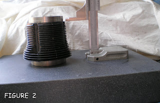
To make an adjustable push-rod you start with a stock push-rod. I prefer the older style because of the smaller head diameter but the later model will also work. (Fig 2 will give you some idea of the difference in head diameter. Some steel push-rod kits use the smaller diameter heads, leading to an error if you check push-rod length with the larger heads.)
Using a hacksaw, cut the push-rod in two. Make the cut approximately in the middle of the rod. Then cut 5/8" to 3/4" from one of the pieces.
Dress the cut ends square with a file. If using the old style, ream the ID with a drill bit suitable for threading to 1/4-20. That would be a #7 but if you don't have a set of number-sized drill bits, you may use 13/64". The later model push-rod has a slightly larger ID and I believe it will accept a 1/4-20 tap without reaming (but check).
Tap each half of the push-rod tube to a depth of at least one inch.
Prepare a section of 1/4-20 threaded rod about 2-1/2" long being sure to chamfer the ends. Run a pair of 1/4-20 nuts onto the rod. Give the threads a drop of oil and screw the rod into the ends of the modified push-rod. The nuts will be used to lock-in the length once it has been determined.
--------------------------------------------------------
Fig 3 shows a handful of parts heading for a fellow engine-builder trapped in the Nevada desert. Since I didn't know what type rockers or push-rods he'd be using, I sent one of the old-style adjustables.
-------------------------------------------------------
Adjustable push-rods are available from after-market retailers but they usually put the thread at the very end of the rod, making them horribly inconvenient to use.
-R.S.Hoover
Thursday, August 9, 2007
Tappets As Field Mice
Back when I built engines for sale (*) I usta haul all that crap around, putting on a Dog & Pony show at fly-in's, swap-meets and chapter meetings, showing folks how easy it was to convert a VW engine for flight and why my engines were a bit different from all those Other Guys.
Waste of time, pretty much. Oh, I sold a few engines, along with lots of Azusa wheels and the little axle I'd made up for them. But most folks wanted an engine '...just like Ken Rand's' or whatever. All tolled, I only sold three with the fan on the clutch-end of the crank. But I think the main reason for my lack of success was telling the truth when someone would ask about horsepower. (Like all air-cooled engines the Volkswagen has specific thermal limitations. Exceed them and your TBO takes a heavy hit.)
Drive all night to get someplace, unload a ton of tools, jigs, fixtures, parts and brochures, then spend the day showing folks how to put Tab A into Slot B, it sorta takes the thrill out of it, especially when you do something dumb such as dumping your tappets on the ground.
Unlike a Lycoming or Continental which is usually assembled around the crankshaft whilst standing on its nose, the VW crankcase has a number of studs anchored in the left-hand case half and you usually assemble the engine with the left-hand case-half open-side facing up on the work-bench or in the fixture. To mate the two halves you pick up the right-hand case-half, align it with the studs and slide it down onto the left-hand case half. The crankshaft and camshaft is supported in the bearing saddles in the left-hand half of the case while the right-hand half has nothing in it except four tappets.
The best excuse in the world for dumping your tappets is that it couldn't happen with the the early VW engines, in which the tappet and push-rod were a single unit. Assembly habits acquired acquired prior to 1960 were liable to make you look like a klutz after that date. Indeed, for a time following the introduction of the forty-horse 1200 engine, dropping your tappets on the floor -- or forgetting to install the damn things -- was almost a National Sport, at least among VW mechanics.
Which is kinda silly because it's easy to not dump your tappets on the deck. All you gotta do is grab a can of wheel bearing grease and smear a light wipe of the stuff under the head of the tappet. When you pushed the tappet into its bore the grease would cause it to stick long enough for you to put the right-hand case-half into position. (But only under the head. Too much grease in a tappet-bore is a bad, bad thing, since oil to the end tappets can only get there by passing through the middle tappets. Lard them up with grease, it was liable to block the push-rod tubes and prevent oil from reaching the end tappets. But a light wipe under the head of the tappet is okay.)
If you were one of those effete-type VW Mechanics with clean fingernails and a ducks-ass hair-cut you'd scrounge an old throttle wire out of the scrap bin, cut it into pieces about a foot long and twist it around the handle of a breaker-bar. Bend the free ends at right angles, trim them to equal lengths and you had a kind of Super Hair Pin you could poke down into the tappet's bores, where the tension of the spring would hold them in place.
Quick like a bunny, hair-pin tappet retainers appeared in all the magazines as an Absolute Necessity at prices ranging from Simply Silly to Absolutely Ridiculous. And remain so today. If you need a pair, make them. Fig 2 shows a pair made from brass welding rod and another pair made from 1/16th inch music wire. The singleton is a retail item.
You can make the things out of any reasonably resilient wire. Music wire, such as used on the VW throttle cable, is probably best but I've made them out of springy bronze welding rod and electrical fish-tape. But Home Alone, 99 times out of a hundred, I reach for the wheel bearing grease, give them a wipe and put the thing together. Which isn't worth a bucket of warm spit if you're 800 miles from home giving a spiel to a buncha guys and the grease is back home on the shelf.
You can try the Stealth Approach, which is to raise the left-hand case-half as near to the vertical as it will go before the crankshaft flops out on the floor. Then you smear a gob of Lubri-Plate on the right-hand lifters, pop them in place and try to get the case-halves aligned before the lifters come oozing out of their bores, which is exactly what they'll do if you get hit with a couple of questions between Tab A and Slot B.
So there I am at some fly-in giving my spiel on Short Block Assembly and there's my right-hand tappets bouncing around on the hangar floor like cast iron mice. Not what you'd call a good impression. But I can honestly say it was the last time I allowed it to happen. I adopted the Hair Pin Procedure. Which worked fine, until...
Let me offer a whiff of reality about doing demos at fly-ins (and one of the reasons I regularly decline such invitations): People steal things. If you don't have a crew of at least three, you're going to lose stuff. Roping-off your work tables helps, assuming you've hauled along enough rope and stanchions. But there's plenty of times when you have to take a pee, someone starts asking questions of your crew and when you return the far end of the table is bare.
Cost of doing business, right? Pass it along to the customer. But sometimes something critical, such as a magneto or prop-hub would wander off and you're left trying to do a demo without all the parts. So one day I'm just getting into the spiel when I notice the tappet retainers have vanished, along with a stack of shims and the magneto puck.
Doing demos, it's best not to count on having compressed air. If you haul in your own compressor you'll also have to provide a suitable extension cord and hoses, all of which is liable to vanish unless you've got it chained to your table. So I got into the habit of using 'canned air.' Back then, it wasn't air of course; usually some fluorocarbon. Nowadays it's liable to be propane mixed with something to render it less flammable. The key point here is that 'canned air' is usually a liquid under pressure, having a very low boiling point, such as minus thirty degrees.
Want your tappets to stay in place? Don't have a pair of hair pins? Left the wheel bearing grease at home? Then turn your can of 'Dust Off' or whatever upside-down and give the push-rod end of each lifter a shot of liquid. It will chill the lifter enough to harden the lubricant, locking the lifters in their bores at least long enough for you to mate the two case halves.
-R.S.Hoover
(*) If you'll dig through your pile of old 'Sport Aviation' magazines ('old' = mid-1970's ) you'll find my ad tucked away there in the back. Same address. Same engines.
Sunday, August 5, 2007
SURFACE PLATE
[AirVW] Re: Oil pump leak
Wed, 24 Nov 2004 05:48:06
--- In AirVW@yahoogroups.com, "Steve Chilcott"
> Bob was correct. When I checked the flatness of the full flow face
> plate I discovered there was a cupped sort of channel across the face
---------------------------------------------------
Well, good for me, then :-)
Of course, I was probably out back sawing up stove wood while the Mechanic-in-Charge of Steve's engine was doing all the work so let's give credit where due, which is to Steve.
There's lots of ways to check for flatness. One is to bridge the part with a known-true straight-edge such as the blade of your machinist's combination square then hold the part so you can see if there's any light between it and the straight-edge. For something like the cover-plate on the oil pump, that would serve as a quick & dirty check.
A better check would be to use a surface plate and some Prussian Blue. You smear the blueing onto the plate with your thumb, drop the cover-plate in the mess you just made and give it a light twist. If it's truly flat the blue will transfer to the entire plate.
Surface plate is a big piece of cast iron or a thick slab of granite. Cast iron surface plates are kinda rare nowadays bu
While cast iron surface plates were inexpensive and not all that difficult to make, they did change their dimensions with the seasons due to the expansion & contraction of the metal.
Granite was more accurate over the long term but flatting a hunk of granite took the task out of the machine shop. Which isn't to say you can't flat granite, just that it isn't a commonly taught skill. Unless you're into optics.
Nowadays you can buy a small surface plate for a very reasonable price but if you're only building one engine there are a number of substitutes that will fill the bill. The one most commonly available is a twelve-inch square of polished granite tile, available from Home Depot. To make it useful, get a piece of well dried 3/4" plywood, seal it up good with thinned varnish and after that cures, bed the tile in a layer of urethane painter's caulk. To ensure the caulking will cure, give the back of the tile a spritz of water before smooshing it into the caulking. Once it cures, the caulk will act as an elastomere, isolating the granite from the wood. (Fig 3. is an inexpensive 9 x 12 surface plate used for flatting, checking valve springs and other low-precision chores.)
Prussian Blue is the other head-scratcher for non-machinists, in that most of you won't know where to get it and will find it rather pricey for just one engine. So use lip stick. Yeah, they always look at me when I say that. Forget it. Go down to the Dollar Store or whatever and look for inexpensive cosmetics. Color isn't important. I generally look for stuff on sale, buy a couple of tubes of whatever.
Prussian Blue (or lip stick) serves as your 'spotting compound' when checking the fit of your valves after being lapped, and of the cylinder barrels in their bores and if the top edge of the barrels is true and the mesh of your cam-gear and lots of other stuff. Lipstick also cleans up nice.
Steve's experience with his leaky pump is a nice example why you can't just bolt parts together and expect to end up with a good engine. The fact it runs is not the definitive test. Virtually any collection of VW parts will run.
The tricky bit -- and the enormous mass of detail not contained in all those swell manuals telling you how to bolt things together -- is what to do to correct the numerous problems that crop up along the way, such as the drips or a tight bearing (or a loose one), valve gears that don't mesh proper or cock-eyed valve train geometry.
Experienced engine builders have found the best solution is to not let such errors occur. To prevent them, they blueprint all of the parts first as individual components then as sub-assemblies, mating them with their associated parts in as many pre-assembly steps as it takes, correcting errors as they are discovered.
This method is an absolute necessity when you have only one engines-worth of parts to work with.
-R.S.Hoover
Wednesday, August 1, 2007
HEADS 102
This photo, stolen from Jake Raby’s web site (http://www.aircooledtechnology.com) is of a Type IV head that has been treated with the full range of coatings.
The black coating on the head is a thermal dispersant that increases the thermal emissivity of bare aluminum by about 8%.
The grayish-white coating on the combustion chamber, the faces of the valves and the head of the pistons is a ceramic-metallic alloy that is a very poor conductor of heat resulting in a higher BMEP for the same CR and amount of fuel.
BACKGROUND
Before there was Yahoo we had eScribe. That’s where the AirVW Group came into being shortly before the turn of the century. (I think it was 1998.) Then Yahoo bought eScribe, promising to maintain the archive of messages. They lied but that’s the norm when there’s money involved.
Unfortunately for the aviation community the archives contained thousands of VW-related messages of real worth, such as the discussion on Thermal Barrier Coatings.
What follows is when the conversation was resumed under Yahoo. It is not complete but for those new to the subject it offers a hint of what has gone before.
---------------------------------------------------------
21 Jan 2003
Ceramic coatings
--- In AirVW@yahoogroups.com, CaptonZap@a... wrote:
>a while back you said you would have a report on the
> ceramic coatings and their effect on engine performance. Anything on that
> front yet?
--------------------------------------------
No.
I've proven to myself that cer-met coatings work. But it has taken me nearly three years to come up with a method of applying the stuff that may be suitable for use by individuals.
The most recent development (or lack of it) was the discovery that while an oven made out of cement-board, using the burner from a defunct water heater, works perfectly well, controlling the thing manually by bobbing about peering through holes at an array of oven thermometers -- does not, in that it simply isn't practical. I saved up for a thermostatically controlled over and it is now on-order. This will hopefully allow me to stuff a coated part into the thing, set the timer and forget about it.
(You can't use your household oven for the more exotic coatings. They contain some seriously lethal poisons that will diffuse into the lining of the oven... and back into your cookies when you're done baking pistons. So you need a spare oven. Since gas is the cheapest source of heat, I made a gas oven using junked parts. But the curing temperature has to be kept within a fairly narrow range [narrower than most domestic ovens allow] with is difficult to do without expensive controls. So I did it manually. And while it worked, it was a major pain in the ass. So I'm trying something else.)
Another reason I'm not ready to post anything on TBC's is because I don't have any quantified data for full-size engines. I've seen some rather remarkable improvements in the one-cylinder lawnmower engines I used for testing but I don't think the data from a 6cid one-lunger can be extrapolated to big-bore VW stroker.
For anyone who isn't familiar with Thermal Barrier Coatings you'll find lots of information on Tech Line's website. TBC's were originally developed to protect the turbine blades in the hot-section of a turbojet engine. And they do. But what's really exciting are the hyper-eutectic coatings. Just as an alloy of lead and tin can be ratio'd to melt at a temperature lower than either of the base metals, it is possible to obtain a unique hybrid coating of ceramic and metal which fuses to the substrate at relatively low temperatures, allowing the stuff to be applied to aluminum engine parts.
In theory, you can build yourself a better engine by simply spraying on some magic stuff then baking it in the oven. In fact, the material has to be extremely clean, the surface to be coated must have a certain texture, the coating must be applied in the right thickness, dried to the right hardness then baked at the right temperature. Some coatings require post-baking procedures. Develop a system for forged mild steel, such a VW crankshaft, and it's liable not to work for cast iron (such as a VW cam shaft) And what works on a cast iron cam shaft may not work on a cast iron cylinder barrel. Most frustrating of all, there is no manual for any of this.
(NOTE: The photo is of a Type IV combustion chamber on one of Jake Raby's race-winning engines.)
Do it right, you end up with a piston & combustion chamber that withstands higher temps and pressures. Or bearing journals that are self-lubricating. Or exhaust valves that shrug off heat. Or an exhaust pipe that runs cool to the touch (!) Or surfaces that radiate 8% more heat. Modern-day magic... once you figure out how to do it :- )
The stuff -- a water-based slurry in most cases -- is fairly expensive. Do it wrong, you end up with a mess. An expensive mess. I haven't spent much in actual dollars -- mebbe five hundred bucks -- but it has eaten up hundreds of hours and all sorts of little jigs and fixtures to hold or rotate a particular part.
(NOTE: $30 for 3 ounces of CBC-1. That’s enough for at least three Volkswagen engines if all of the parts are prepped and can be sprayed at one time. July 2007)
For those of you with the money, there are shops that will apply your coatings for you. But as I said, it's fairly expensive. On the VW heads, for example, you may elect to use a barrier coating on the chamber, valve heads and exhaust port, plus a friction reducing coating on the valve guides & stems, plus a thermal dispersant on the outer fins and the floor of the valve gallery. Unfortunately, none of the shops I've talked to had ever applied thermal dispersants to finned aluminum heads. (And now I know why :-)
(NOTE: As of July 2007 it costs about $450 to have a professional shop do a basic coating job on a VW engine. But not every Tech-Line ‘approved applicator’ does engine coatings. Most are just powder-coating shops that also do a few of Tech-Line’s exhaust system coatings.)
Since the stuff ends up becoming a part of the metal to which it is applied, it is also useful as a surfacant, allowing you to protect parts against corrosion. The self-lubricating properties are especially interesting to gunsmiths and machinists.
-R.S.Hoover
-------------------------------------------------------
23 Jan 2003
Re: Coatings and ovens
--- In AirVW@yahoogroups.com, "Jack Hohner
> These coatings sound like they would really extend the durability of
> the valves, expecially when combined with Bob's HVX oil flow
> modifications. But it sounds like it might be easier just to do a
> valve job?
> ---------------------------------------
Dear Jack,
You're probably right. And you're not the first to raise this point :-) In fact, it goes quite a bit deeper than that.
None of the things I do to an engine are especially significant of themselves. I spend a couple hours cleaning all the casting flash out of the heads and opening up the air-ways around the exhaust stacks. To the casual observer the heads looks the same. And his engine runs about the same as mine. If he's got his CHT under the spark plug, it will even say his heads are as much as 100 degrees cooler than mine, which picks off CHT nearer the exhaust stack. So his valve gallery is dark with cooked on varnish and he needs a valve job after a hundred hours and I don't. No varnish, no sticking, compression in the 120's and even all around, leak-down a scant 10%.
A hundred hours is a full summer of flying fun and the local VW shop will probably do his valves for $25.
Odds are, he'll never makes any really long flights; not over the ocean nor the desert or the Sierras. For his kind of flying a dune buggy engine makes good sense. To him. Until it lets him down. And after it does, assuming he lives through it, he'll do what most guys do in that situation, damn all Volkswagens out of hand and go to a different engine... if he even continues to fly.
------------------------------
The coatings aren't just thermal barriers. Some are lubricants. Others protect the surface from corrosion, allowing an inexpensive and easily fabricated carbon steel part to work as well stainless.
The oven is actually a fairly minor point. (The cement-board jobbie was not my first effort :-) Getting the surface clean is trickier than it may appear -- most of the coatings are water-based. That means ANY oily residue will give you fish-eyes. The surface texture is also critical to the final finish. Coarse sand works pretty well for aluminum, such as the piston tops and combustion chambers, but you need silicon carbide for the valves. (NOTE: I now use #120 aluminum oxide.) Then comes laying on a uniform coating of whatever material you're trying to apply to that surface. Most of them you can apply with an air brush but getting down into the exhaust port is fairly tricky and air-borne application doesn't work at all on a deeply finned surface.
-----------------------------------------
Although it isn't entirely correct I tend to think of the modifications to the lubrication system as COOLING enhancements, whereas the tungsten- and molybdenum-based coatings applied to the cam and bearings and crank and valve stems... are the real lubrication enhancements. The thermal barrier coating applied to the pistons and chamber may result in a slight increase in torque. Or they may not. (In a lawn-mower engine the best I can say is that the treated engine did the same amount of work on slightly less fuel.) But applied to the exhaust system TBC's can have a profound effect on getting hot air to the carb and preventing rust.
-----------------------------------------
Spritzing eight valves with TBC then baking them isn't much trouble, not when you're spraying other parts too. But as you've pointed out, it's tough to justify ANY of this stuff -- coatings or modifications - - if a guy only wants to buzz around his south-forty on a warm summer evening.
I gave up arguing the point years ago. The engines can speak for themselves.
-R.S.Hoover
-------------------------------------------------------
25 Jan 2003
Re: Coatings and ovens
--- In AirVW@yahoogroups.com, "Jack Hohner
>
> Actually, I was hoping that with the full flow oil mods, one might
> expect the valves to hold up for 1000 hours. And then pull the
> heads, find minimal wear and bring them back to new specs. Is this
> unrealistic?
>
Dear Jack,
I think 1000 hours is unrealistic for carbon steel valves with solid 8mm stems. With Type IV heads you can use sodium-filled exhaust valves having 10mm stems. The larger stems are known to have a better wear factor (most airplane engines use valves with 1/2" stems... 13mm in diameter) but I don't know if they could go a thousand hours. --------------------------------------------
> I like the coating mods and probably should do them while I am doing
> the oil flow mods. From the discussion, it sounded like the coatings
> are pretty tricky.
------------------------------------------------
Some of them have been. For me :-) I haven't seen any real 'discussion' on the application of coatings. In fact, over the last three years I haven't run into anyone else trying to teach themselves how to apply the stuff, other than the usual nay-sayers.
---------------------------------------------------
> Is the friction coating a bit less fussy to apply
> than the TBC? I thought I read some reference along those lines. It
> seems that would help with the valve guide wear, if one is balancing
> return on effort expended.
>
----------------------------------------------------
WSX (tungsten disulfide) is a dry powder that is burnished into an oil-free metal surface. I think this is a good choice for applying inside of things, such as valve guides and the bearing surface of rocker arms, the push-rod 'cup' in the tappets & rockers.
(NOTE: It takes a fairly heavy pressure for the stuff to burnish-in properly.)
I think it's fair to assume that all engines will eventually use coatings on ALL surfaces. A big question for me right now is which coating is best for what surface. And just to make it interesting, about the time you've figured out how to apply a particular stuff, they're liable to introduce something that has better specs. Do you start all over again? (I have, a couple of times.) Or run with what you've got?
(NOTE: My most recent batch of Tech Line’s ‘CBC’ has a different viscosity from the last batch, requiring a smaller nozzle on the spray gun and some minor changes in how the stuff gets applied.)
One problem I have with the coatings is that aside from using them up learning how to use them, once I have a workable receipe I immediately see applications for the procedure. I've just moly- coated my first 10" saw blade, for example. And yes, it cuts smoother.
-R.S.Hoover
---------------------------------------------------------
Re: Copper State
(NOTE: Someone proposed I conduct a ‘VW Seminar’ at the Copperstate Fly-in.)
--- In AirVW@yahoogroups.com, Andre Viljoen
>
> How about it Bob? What's your feeling?
> ---------------------------------------------
Dear Andre (and the Group),
I appreciate the thought but I'm pretty busy right now. And I really haven't anything to say that you can't read for yourself in the manuals from Continental, Lycoming, Pratt-Whitney or Wright.
Later this fall I hope to have some quantified comparitive data from my thermal barrier coating experiments. (Which ISN'T in any of the manuals.) The preliminary work with one-cylinder engines indicates TBC's put an advantageous kink in the BMEP curve for air cooled engines. Extrapolation from 6cid to 140cid offers some evidence that the three years of experiments may pay off. Or they may not.
The truth is, I'm not entirely clear as to the purpose of a 'seminar' on engines since an engine is perfectly capable of speaking for itself. Indeed, over the years I've found it best to let the engines have the final word since they tend to do so anyway :-)
-R.S.Hoover
----------------------------------------------------------
14 Oct 2003
Re: Enlarging jug fin area
--- In AirVW@yahoogroups.com, "Nicholas Cafarelli"
> I have been searching online for a while trying to find out if anyone
> has ever experimented with enlarging VW jug fins.
> -------------------------------------------------
Dear Nick (and the Group),
I've tried this approach. And wrote about it... somewhere.
Clamping doesn't work. This was a trick tried by the motorcycle crowd way back when as a means of squeezing a few more hp out of two- strokers. While it looks good on paper, the clamped-on extensions do not form a good thermal bond with the existing fins but they do a nice job of obstructing the flow of air to them.
I welded extensions to the fins and got excellent heat-flow across the weld. But it was very time consuming and after making the mod, which I called my Fat Fin heads, they would not fit on my existing tooling.
The exhaust stack, especially its 'elbow' right where the valve guide is installed, is the hottest part of the head. You can add a couple of eyebrows to the top, from the diagonal stay between the spark plug hole and the middle stud(s)but you can't go out any farther than two fins (about 5/8") or you'll obstruct the spark plug hole.
Adding more fins doesn't help unless the heat can easily flow INTO the new fin area, and there is good air-flow OVER the new fin area. With Type I heads you run into both of these problems. It does no good to add fins under the exhaust stack since there's no convenient way to get air to them. Welding fins perfendicular to the existing fins, outboard of the exhaust stack, does little good because heat can only get into them through a narrow bridge adjacent to the lower exhaust stud.
You can add a significant amount of fin area to the eight large fins but based on temperature readings, increasing the size of the four fins closest to the crankcase was pretty much a waste of time. More fin area means more air-flow down THRU the fins. Causing more air to flow down through COOL fins didn't help the situation up near the exhaust stack. And you can't extend those fins because OF the exhaust stack.
Take a look at Porsche heads. To get more cooling you have to do something similar to what Porsche has done, which involves moving the exhaust valve and relocating the stack. Or look at the Type IV, which moved the stack to the bottom of the head, thus freeing up the entire end of the casting for cooling air flow.
I really wish this experiment had worked better than it did. It was a lot of work and once modified, the head could not be used on a vehicle since they would no longer fit under the stock shrouding.
-------------------------------------------------------
Another approach to the problem sounds almost too easy to be true.
In order to add valve stem seals I have to replace the guides even on brand new heads so I generally punch them out pretty early on in the process, usually right after I've opened up the chambers and cc'd them. after the guides have been removed is the perfect time to clean up the castings down inside the ports. For the exhausts this usually involves the removal of a significant amount of metal, especially if there are any inclusions (ie, core debris). The exhaust ports on a stock head are pretty small -- under 1-1/4" -- and I usually open these up to about 1-3/8" to match the exhaust manifold.
When you get done cleaning things up the surface should be perfectly smooth with about a #600 finish. (According to NASA, a smoother surface will not flow any better.)
In theory, the greater surface of the ported exhaust stack will absorb more heat so it makes good sense (to me) to apply a thermal barrier coating.
If you come up with a good method of applying a TBC to an exhaust port by spraying, please let me know. I tried all sorts of extended nozzles and so forth but finally resorted to painting the stuff on with a foam brush, trimmed down just for that purpose.
Adding fin area allows you to couple more heat to the atmosphere; you should be able to generate MORE heat without seeing the temperature rise. Thermal Barrier Coats slows the adsorption of heat by the surface to which it is applied and MAY allow you to achieve the same goal for much less effort.
---------------------------------------------------
In a related vein, I have received a couple of queries regarding comments made about 'thermisters,' which is my mis-spelling of thermistor. Specifically, the bit about dipping them in heat-sink compound then wadding them into a piece of aluminum foil. The object there was to provide a good thermal path between the fins of the head and the thermistor; you poke the things right down to the bottom of the fin using an ice-cream stick or similar.
Thermistor do NOT read directly in degrees of temperature (unless you're very lucky :-) All they do is alter their resistance according TO the temperature. You must compare their resistance to a calibrated thermometer to make a chart or conversion table. Once you find a thermister having a usable range, buy a batch of them. So long as they are from the same batch, even surplus thermistors are generally close enough so that you only have to calibrate a couple of them to know how the whole batch will read.
Thermistors come in two flavors. Negative types, their resistance FALLS as they get hotter. For direct reading, you generally feed these a voltage and measure that; the hotter the temp, the more voltage you'll see. Positive types, their resistance INCREASES as they get hotter. You can usually read these directly using the ohms- scale of a sensitive multi-meter. But in each case, the numbers on the meter are NOT degrees of temperature; you have to work that out during the calibration process.
The whole idea is that you end up with a reasonably accurate THERMOMETER that's about the size of a grain of rice and can be applied wherever your ingenuity will allow. If you can afford the Good Stuff, Boeing sells some special silver-filled epoxy used to bond thermistors to aluminum. Or you can do like I did, wad them into aluminum foil and clip them to the fins with paper clips (!) or stuff them down between the fins, or fasten them using every other method you can imagine.
You end up with wires running all over the place, hopefully marked according to the LOCATION of the thermistor.
Don't try to get too sophisticated here. YOU become the limiting factor in that you can only make a certain number of readings on each run before things heat up. It would be nice to rig a computer so you could plot temperatures in near real time... Maybe one day. (My test stands already looks like Dr. Frankenstein's basement :-)
-R.S.Hoover
----------------------------------------------------------
5 Dec 2003
To All:
I always polish the combustion chamber and top of the piston. I won't be doing that on my next engine because those parts will be treated with a cermet thermal barrier coating.
I always smooth the as-cast portions of the intake & exhaust ports but polish only the exhausts, or in this case, apply a TBC.
Two people have contacted me (over a three month period) asking why I mentioning polishing in one post then apparently reverse myself and refer only to smoothing in another.
The answer is in the context of the posts but since two people have managed to read it wrong I obviously haven't stated the matter clearly enough.
The reason for polishing a surface is to RETAIN THE HEAT OF COMBUSTION. In the chamber, you want the heat to hang around as long as possible so as to develop the highest pressure and the least amount of heat to be absorbed by the piston & combustion chamber walls. Polishing (or thermal barrier coatings) accomplishes that.
Once the exhaust valve opens the exhaust port must respond to both heat and gas-flow. Polishing addresses both issues, in that you want the best possible gas-flow with the LEAST heat-transfer into the head.
On the intake, simply SMOOTHING the as-cast surface is sufficient since the task here is to facilitate the smooth flow of fuel/air mix into the chamber. NACA and Pratt-Whitney have shown there is no improvement in flow beyond a #600 surface finish.
-R.S.Hoover
---------------------------------------------------------------
11 Nov 2004
Other Things That Work (Valves & cooling)
Thermal barrier coatings. These are hyper-eutectic compounds which form a ceramic-metallic alloy with the base metal at low temperatures but once cured, withstand exhaust gas temps.
When bonded to a surface TBC's reduce the ability of that surface to absorb heat. The material was developed to protect the turbine blades in the hot section of jet engines. By comparison, temperatures in the VW combustion chamber are relatively cool.
Coating the heads & neck-area of the exhaust valves prevents them from picking up so much heat. Coating the exhaust stack prevents the heat from being absorbed by the head when the valve opens. Applying a high-temperature dry-film lubricant to the valve stem & guide promotes better transfer of heat between them by allowing you to run tighter clearances without risk of galling or sticking.
Coating the top of the piston and the combustion chamber prevents those surfaces from absorbing heat as readily, resulting in higher sustained temperature of combustion, giving a higher BMEP for the same compression ratio.
Bottom line: Less heat appears in the heads & oil (it shows up in the exhaust) and a greater amount of torque appears in the crankshaft -- all for the same amount of fuel.
The dry film lubricant is tungsten disulfide and is easy to apply. Simply degrease the part (totally -- boil them in TSP) then RUB the dry powder onto the surface and burnish it in. It will form a molecular bond with the metal. Also works for all of your bearing surfaces and the base metal of your cam & lifters, rocker arms & shafts, push-rod ball-ends and the cam & distributor gearing. The stuff is expensive but just a dab will do ya.
The hyper eutectic coatings with which I've been experimenting produce a ceramic-zirconium alloy... if you apply it correctly. That means proper surface preparation (typically blasting with media to produce a uniformly textured surface) spraying on exactly the right thickness of the WATER-BASED compound, allowing it to dry then baking it at the correct temperature for the required amount of time followed by allowing it to cool in place.
The tricky bit is that some TBC compounds (there's half a dozen of them) do better with some metals than others, and each DEMANDS slightly different procedures in the application, cure, bake and cooling. Mess things up and you get to start over, often with a new part because this stuff don't wanna come off.
The stuff I'm using comes from Tech Line Coatings. They have a web site and they will sell to individuals. But they don't have a lot of air-cooled engine experience so don't expect to find no-fault cook-book type instructions. I've been working with the stuff for about five years now and I've gotten fairly good at it, meaning I don't fuck up as often as I used to, but I'm still a long way from being able to provide how-to info, other than the above. But it's honest stuff, not a pipe dream, and it really does work... when properly applied.
Most engines builders will immediately benefit enormously from using Tech Line's virtually fault-free exhaust system coatings. Main advantage here is that once coated, the durability of mild steel tubing approaches that of stainless steel.
They also offer thick-film lubricants -- stuff that needs to be baked on -- that should be the cat's pajamas for crankshafts... if you've got the balls to use it. I've done just one stock crank with it; I didn't have the guts to try it on an expensive stroker until I've actually seen how it does on a real engine. But it's wizard stuff on saw blades (!) and the like. (Did I mention these are experiments?)
Build your own engines, you become the Mechanic in Charge. That means you sometimes have to try new stuff, which is always a risky business.
Doing the valves, you're pretty safe. Valves aren't very expensive and you probably have a box full of old ones on which to practice. You should have a blasting cabinet and a good air supply. You'll also need an air brush and a variety of jars. (See my article on the subject.) Getting a UNIFORM coating is one of the trickiest parts of the procedure. Heads are a bitch but valves are pretty easy. You need a rack to hold them while you blow on the coating and another rack to hold them while they bake & cure. (If you use the same rack, the TBC welds the valve to the rack.) Once cured, you'll have to cut through the coating when you re-lap the valve. The oven should be electric, accurate and NOT used for cooking. (Some of this stuff is toxic.) Curing temp is typically 300 to 350*F, depending on which coating we're talking about. But forget about using a gas oven unless you can isolate the burner's combustion gases from the object being cured; with some coatings gas heat leaves a slightly stippled surface (probably from the water being produced by the combustion of natural gas (ie, methane) ). The temperature has to be accuately controlled; if the thermostat hunts too much some coatings end up with a surface like an old oil painting.
Doing heads are the trickiest because you're looking at three different coatings & methods. My oven can only hold one head at a time so it's pretty slow-going with more than one engine in the works.
-R.S.Hoover
PS -- Funny (?) Story: I've got one 'coated' engine running. Stock VW bus engine, running on the stand. About 20 hours on it so far running without any load (ie, flywheel; using about 1 gph). It has proven to be an extremely boring engine. No surprises at all. And no symptoms either; it appears to be totally bulletproof.
The funny part is that I did have a couple of problems, which got me all excited, ready to tear that sucker down so I could see the PROOF that this miracle stuff DID NOT WORK.
The first problem proved to be a dirty carb. (The test stand is out in the weather; shit happens.) The second was a bad ignition lead. (Only five or six years old...)
At the present price of gas (My last fill up cost me nearly $100) I'm about to give it up as a bad job, go ahead with the bigger engines, risk my ass with some air under the wheels. But I thought it was funny as hell going to Defcon One and having it turn out to be a bad wire :-) (Is that a MISS? Bad valve? Burned piston? TBC spalling off the combustion chamber? Contaminated plug? Broken adjuster? Bent push-rod?) I was all ready to roll it into the shop, start stripping her down to find out what went WRONG, as is the usual case with most experiments.
But four years and counting, finally got to a real engine (most of the experiments were on lawn mower engines) and the sonofabitch refuses to give me a real problem to work with! (After about 30 hours I'd like to load it up to around 50% and put about a hundred hours on it, then tear it down. But at the present price of gas, that's not going to happen.)
Maybe it's time I started thinking about a vacation :-)
------------------------------------------------------------------
12 Nov 2004
Re: Other Things That Work (Valves & cooling)
--- In AirVW@yahoogroups.com, "Jack Hohner"
> Can this stuff be sprayed on
> electrostatically?
----------------------------------------------
I don't know. But I know a good way you can find out :-)
----------------------------------------------
> Is this stuff sensitive to airflow in the oven.
----------------------------------------------
I think it's fair to say that it is. I've tried both a rotisserie and a fan, and both together, as a means of evening out the flow during the fluid phase. The fan worked best. Any motion in the part usually resulted in an uneven surface texture.
------------------------------------------------
As for drawing on the experience of others, I certainly tried, including several posts here and to other VW-specific Groups. While there are plenty of NASCAR types using it, all of their applications are for water-cooled engines, mostly on steel parts. Even with aluminum heads, the fact they were water-cooled puts them nearly 300 degrees below the reality of flying Volkswagens.
Lots of good poop about exhaust systems, though. In fact, there's any number of shops that specialize in applying TBC's to exhaust systems. Ditto for pistons. But start talking air-cooled engines and they always get a call on another line :-)
Leonard, the fellow who runs Tech Line, was very helpful but admitted right up front he didn't have a lot of data for air cooled applications and would like to know how my experiments came out. It would have been even friendlier of him to pick up the tab (this stuff is expensive.. for me) but I imagine he hears a lot of BS from wannabee engine builders.
Personally, I'm not comfortable with the system even now; I would prefer to say nothing until I could back it up with several hundred hours of flight. But right now I've no idea when or even if that will be. I chose to mention TBC's because of the thread on oil-cooling the heads, a path I explored nearly twenty years ago and found less than ideal. Ditto for water cooling. Best bet is to start with a completely new casting but that would put the engine out of reach of the typical homebuilder.
I've tried to find the best reliability at the least cost, using methods and procedures that ANYONE could duplicate. If the conversion requires too much machining or too many special parts, we may as well forget the VW as a power plant for grass-roots aviation and start looking at industrial engines and airframes large enough to carry them.
-R.S.Hoover
-------------------------------------------------------
23 Nov 2004
Re: Questions on Thermal Barrier Coatings (Mr. Hoover)
--- In AirVW@yahoogroups.com, "enginegeek2"
>
> Dear Mr. Hoover,
> I don't know if you have seen this link and what these folks are
> doing: http://www.aircooledtechnology.com/coatings.htm
> ---------------------------------------------
I think it's fair to say Jake and I are on generally friendly terms. But as you can see from the photo of the 2332, there are lubrication mods I do to my engines that Jake doesn't do to his.
(NOTE: If you’ll poke around Jake’s web site you’ll find some nice things he has to say about me with regard to the design of his ‘Down The Middle’ cooling system. It was kind of him to say so publicly but the truth is, most professional engine-builders are known to one another and while our methods vary in minor ways the performance and durability of our engines shows that we’re pretty much singing off the same sheet of music.)
Most of Jake's business is focused on Type IV's whereas I'm still trying to find the best combination of conversion techniques for turning the Type I into a reliable aircraft engine. For example, Jake doesn't like hydraulic lifters whereas they've been standard in small aircraft engines since the 1930's.
One thing the photos do show is that however we mananged to get there, Jake and I appear to have arrived at the same destination. Best example of that is probably the exhaust valve treatment. (Compare the photo to the HVX drawings.)
The photos also show that Jake (or whoever is doing his coatings) appears to have solved a problem that continues to baffle me, to whit, application of thermal-transfer enhancers to the exterior of the heads. (ie, thermal dispersants) The tricky bit (for me) has been to get a uniform coating all the way down into the bottom of the fins. Someone has suggested electrostatics as the best method and they may be right. Otherwise, based solely on their appearance, my home-grown methods appear to be achieving about the same results.
(NOTE: It turned out that electrostatic application was NOT as efficient as applying the coatings in a water-borne medium. See the Tech-Line newsletters.)
The consumer-grade coatings offered by Tech Line, meaning those sold to individuals, are not toxic, unlike some sold by Tech Line for commercial applications.
Although 'kiddie trade' was originally coined to reflect sales of cheap appearance-items to youngsters (ie, mostly imported chrome junk) with the demise of dealer-support for air cooled Volkswagens, the term has come to mean any immature, technologically naive owner of an old VW; age and the price tag have nothing to do with it. For some real examples simply see the rec.autos.makers.vw.aircooled Newsgroup. You will find several examples of individuals, some in their fifties, who have spent incredible amounts on their antique ride -- including a few who have bought Jake's engines -- only to tear them up. Never their fault, of course :-)
-----------------------------------------------------
The whole idea behind my experiments with TBC's was to see if they might be applied to the one-man, one-engine situation we have in homebuilt aviation. My general conclusion is that they can. But I suspect they will not be. Despite a fairly high level of interest in flying Volkswagens, the actual number of builders (or even pilots) turns out to be remarkably small and as a group, do not appear especially adept in the mechanical arts. The idea of setting up some kind of cottage industry to provide coated parts specific to our needs is probably not valid for the same reason: there simply aren't enough of us.
-R.S.Hoover
---------------------------------------------------------
4 Dec 2004
To All:
I dropped a line to Jake Raby asking if he was doing his own coatings.
He's sending the parts out to:
Calico Coatings,
6400 Denver Industrial Park Road,
Denver NC 28037
Telephone, fax and web Tel: +888 236 6079 Fax: +704 483 2149
http://www.calicocoatings.com
Please note, the name of the town is Denver but the State is North Carolina.
I am trying to develop TBC application & baking procedures specific to the VW engine and which any homebuilder can use. This is not a business; I don't have anything to sell and I'm not interested in doing parts for other people.
Those of you who have written to me (or Jake) in this regard should address your queries to Calico.
-R.S.Hoover